
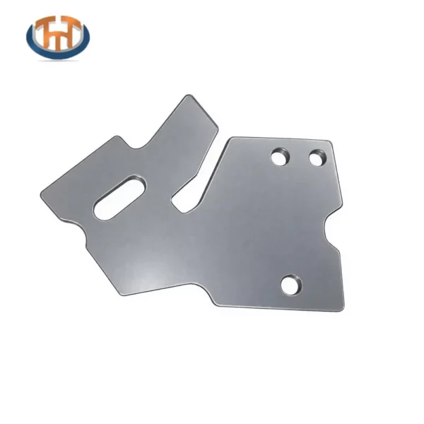
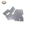
Right Engine Mount Bracket Stamping Die
The Right Engine Mount Bracket Stamping Die is developed for forming a right-hand engine mounting bracket used in an automotive mounting system. Unlike a simple flat mounting plate, an engine mount bracket normally combines several functional surfaces, bends, openings, and locating features into one three-dimensional sheet metal component.
The engineering drawing supplied for this project identifies the component as a right engine mount bracket, with drawing reference 860075689and a component mass of approximately 0.488 kg. The drawing contains multiple views and dimensional references defining the geometry of the finished component.
For this type of component, the stamping die is developed around the relationship between the formed surfaces and the mounting features rather than focusing only on the external outline of the part.
This makes the project particularly relevant to automotive manufacturers looking for a custom engine mount bracket stamping die based on approved 2D drawings, 3D CAD data, material specifications, and production requirements.
Engine Mount Bracket Tooling for Automotive Applications
An engine mount bracket has a functional role within the vehicle assembly. Its geometry determines how the component interfaces with surrounding parts, fasteners, mounting surfaces, and adjacent structures.
This means the tooling development needs to consider more than the appearance of the stamped part.
Important areas may include:
- Mounting feature location
- Formed surface position
- Bend angles
- Hole-to-edge relationships
- Distance between functional features
- Part orientation
- Local deformation
- Final assembly clearance
The supplied drawing shows a formed right-hand bracket with multiple geometric relationships that need to be maintained during manufacturing.
For HONGXING, the objective of the die development is to convert the approved component geometry into a repeatable manufacturing process while maintaining the required relationships between these features.
For projects involving more general automotive body components, HONGXING also develops automotive stamping dies for body structural components.
Right-Hand Configuration and Part Orientation
The component in this project is specifically identified as a right engine mount bracket.
Right-hand and left-hand automotive components cannot always be treated as interchangeable tooling simply by changing the orientation of the part. Their forming surfaces, feature locations, tooling references, and production requirements need to follow the approved engineering data for the specific vehicle application.
For a right-hand engine mount bracket, tooling development therefore begins with a clear understanding of:
- Part coordinate system
- Forming direction
- Functional mounting surfaces
- Hole locations
- Bend transitions
- Reference features
- Part removal direction
Correct orientation is especially important when the component contains several intersecting formed surfaces.
The tooling concept should ensure that the component remains correctly positioned throughout the relevant forming operations.
Designing the Die Around Functional Features
One of the key considerations for an engine mounting component is the relationship between its functional features.
A mounting hole may appear simple when viewed individually, but its position can be affected by surrounding forming operations. Bending or local forming can change the relationship between a hole and the mounting surface if the process is not properly controlled.
For this reason, an engine mount bracket stamping die should be developed by considering the complete feature network of the component.
The engineering review can examine:
Mounting Features
The location of mounting holes and other attachment features needs to correspond with the approved component geometry.
Formed Surfaces
The die must create the required three-dimensional shape while maintaining the intended relationship between different planes.
Bend Transitions
Changes in direction can influence local deformation and should be considered when establishing the forming concept.
Part References
Suitable locating references help establish consistent positioning during production.
Final Geometry
The completed component should be evaluated against the applicable engineering requirements rather than judged only by its external appearance.
This feature-oriented approach creates a different tooling development focus from a conventional description of automotive stamping dies.
Forming Strategy for Engine Mount Brackets
The supplied component has a three-dimensional bracket configuration rather than a simple planar shape.
Depending on the final material, thickness, press conditions, production quantity, and approved process plan, different combinations of blanking, piercing, bending, forming, trimming, or sizing operations may be considered.
The exact sequence should be established during the engineering stage.
A suitable process plan may need to answer questions such as:
- Which features should be created before major forming?
- Which features should be formed after bending?
- Where should the part be located during each operation?
- How can movement of the blank be minimized?
- Which areas require additional forming support?
- Is a final sizing operation necessary?
- How should part removal be handled?
These questions are important because the manufacturing sequence can influence the final dimensional condition of the component.
HONGXING can develop the tooling concept according to the actual component data rather than applying one standard process to every automotive bracket.
For projects where the customer is evaluating different die structures, HONGXING also provides different tooling concepts such as Single Hit Dies for automotive stamping and other customized stamping solutions.
Controlling Feature Position During Forming
For an engine mounting component, dimensional control is closely connected to assembly performance.
If forming causes excessive movement or distortion, the final position of a mounting feature may change relative to another feature.
Therefore, tooling development can focus on controlling the part at several stages:
- Initial positioning
Establish a consistent reference before forming begins. - Intermediate forming
Support the component while its geometry changes. - Local feature formation
Maintain the required relationship between holes, bends, and formed surfaces. - Final shaping
Establish the finished three-dimensional geometry. - Dimensional verification
Compare the produced component with the approved engineering data.
This approach is particularly useful for brackets where several dimensions are functionally related.
Managing Springback and Local Deformation
Sheet metal forming can introduce dimensional changes after the forming load is released.
The amount of springback depends on factors such as material characteristics, geometry, bend conditions, tooling design, and process parameters.
For this reason, springback should be considered during tooling development rather than addressed only after production begins.
Depending on the component requirements, engineers may evaluate:
- Forming direction
- Bend radius
- Tool surface geometry
- Material behavior
- Restraining conditions
- Local forming support
- Final sizing requirements
The objective is to develop a process that produces the required component geometry consistently.
For more general sheet metal forming applications, HONGXING also provides Automotive Sheet Metal Forming Die solutions.
Engineering Development of the Stamping Die
The development of a Right Engine Mount Bracket Stamping Die normally begins with the approved product information.
The engineering team can review:
- 2D engineering drawings
- 3D CAD data
- Material information
- Sheet thickness
- Production quantity
- Available press equipment
- Dimensional requirements
- Customer quality standards
The purpose of this review is to establish a tooling concept that matches the actual production conditions.
Instead of selecting a die structure solely according to the product name, the tooling design should be based on the component geometry and manufacturing requirements.
This is particularly important for engine mounting brackets because the functional areas of the component may require different forming considerations.
From Tool Design to Tryout
After the tooling concept is established, the manufacturing process can progress through several stages.
Engineering and Tool Design
The component geometry is evaluated and the die structure is developed according to the approved manufacturing concept.
CNC Machining
Critical tooling components are machined according to the finalized design data.
Die Fitting and Assembly
Individual components are fitted and assembled to establish the intended tooling relationships.
Tryout
The assembled die is tested to produce trial components under appropriate production conditions.
Part Evaluation
Trial components can be measured against the applicable engineering requirements.
Tool Adjustment
If the trial results identify areas requiring improvement, the tooling can be adjusted before final approval.
This engineering-to-tryout workflow helps bridge the gap between a digital component model and a production-ready stamping process.
Engine Mount Bracket Stamping Die and Production Consistency
The purpose of a production die is not simply to produce one acceptable sample.
The tooling should be capable of supporting repeatable manufacturing over the intended production cycle.
For an engine mount bracket, repeatability can be influenced by:
- Part positioning
- Tooling condition
- Forming consistency
- Material variation
- Press conditions
- Tool maintenance
- Process control
A well-developed tooling concept therefore considers both the initial part approval and the practical requirements of continued production.
This production-oriented approach is especially important for automotive components that must be assembled repeatedly across a vehicle production program.
Application of the Right Engine Mount Bracket
The component represented in the supplied drawing is a right-hand engine mount bracket. Its three-dimensional geometry includes formed areas and functional features that must correspond with the approved engineering definition.
The final application of the component depends on the customer’s vehicle platform and engineering specification.
HONGXING therefore does not assume a universal vehicle application for the part. Instead, the tooling is developed according to the customer’s approved drawings and manufacturing requirements.
This approach allows the same engineering methodology to be applied to different engine mounting components while keeping the tooling specific to each individual part.
Technical Information
| Item | Specification |
|---|---|
| Product | Right Engine Mount Bracket |
| Tooling Type | Engine Mount Bracket Stamping Die |
| Component Position | Right-Hand |
| Drawing Reference | 860075689 |
| Component Mass | Approx. 0.488 kg |
| Application | Automotive Engine Mounting System |
| Manufacturing Method | Sheet Metal Stamping and Forming |
| Component Geometry | Three-Dimensional Formed Bracket |
| Tooling Design | Customized to Approved Engineering Data |
Note: Material grade, sheet thickness, press tonnage, die dimensions, and exact operation sequence are not specified in the supplied drawing information available for this product, so these values are not listed as assumed specifications.
HONGXING Right Engine Mount Bracket Tooling
HONGXING develops customized automotive stamping dies for sheet metal components based on customer engineering data.
For an engine mount bracket project, the tooling development can focus on the specific relationships between the mounting features, formed surfaces, bends, and reference areas rather than treating the component as a generic automotive bracket.
The engineering scope can include:
- Product and tooling feasibility review
- Stamping process development
- Die structure design
- Tool component manufacturing
- CNC machining
- Die fitting and assembly
- Tryout
- Tool adjustment
- Dimensional verification
HONGXING is part of TTM GROUP and focuses on automotive stamping die and tooling development for automotive manufacturers and Tier 1 suppliers.
For customers evaluating different automotive tooling approaches, the company’s portfolio also includes automotive structural stamping dies for more complex vehicle structural components.
Customized Engine Mount Bracket Stamping Die
Every engine mounting component has its own combination of geometry, mounting requirements, material characteristics, and production conditions.
For this reason, an engine mount bracket stamping die should be developed from the actual component data instead of using a standard tooling configuration.
If you are developing a right-hand or left-hand engine mounting bracket, HONGXING can review your:
- 2D drawing
- 3D CAD model
- Material specification
- Sheet thickness
- Production volume
- Press information
- Dimensional requirements
The engineering team can then evaluate the component and recommend an appropriate tooling concept.
For related automotive stamping applications, you can also explore HONGXING’s automotive stamping die solutions and automotive stamping die projects.
Send your component drawing or CAD data to HONGXING for a customized tooling evaluation and quotation.