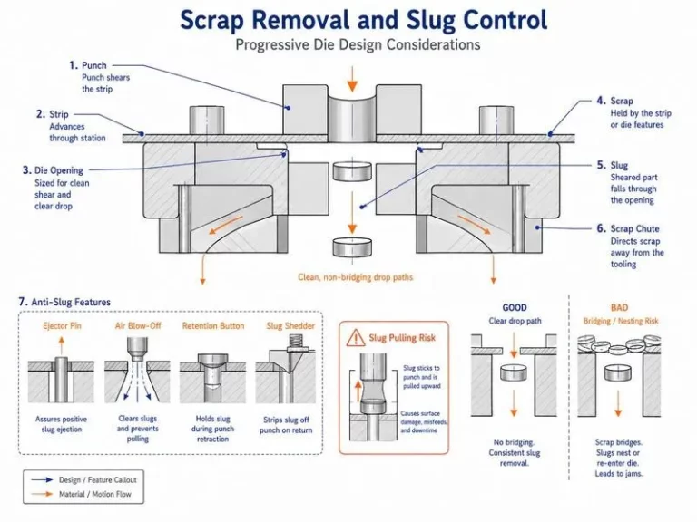


In automotive stamping, the movement of metal scrap is an important part of tooling design that can easily be overlooked during early engineering discussions. While much attention is usually given to forming accuracy, cutting quality, and dimensional requirements, the way scrap leaves the die can also affect production reliability.
During blanking, piercing, trimming, and other cutting operations, metal offcuts must be transferred away from the working area. If scrap accumulates inside the die, interferes with moving components, or fails to reach the intended collection point, the result may be unexpected downtime, die damage, surface marking, or additional operator intervention.
For automotive manufacturers operating high-volume stamping lines, effective scrap evacuation design helps create a cleaner, more predictable production process.
This article explains the main engineering considerations for designing scrap evacuation systems in automotive stamping dies, from scrap generation and discharge geometry to press integration and production validation.
1. Why Scrap Evacuation Matters in Automotive Stamping
Scrap is generated whenever a stamping operation removes material from a blank or partially formed component. Typical examples include piercing holes, trimming component edges, and cutting away unwanted sheet metal.
Depending on the part geometry and die construction, scrap pieces may vary in size, shape, weight, and stiffness. Some offcuts fall freely under gravity, while others can remain attached to the strip, rotate during discharge, or become trapped between tooling surfaces.
These differences influence how scrap should be handled.
An ineffective discharge arrangement may create several production problems:
- Scrap accumulation inside the die.
- Interference with the next press stroke.
- Scratches or dents caused by trapped metal pieces.
- Unexpected press stops for manual cleaning.
- Damage to cutting edges or nearby tooling components.
- Increased risk during die inspection and maintenance.
The objective of scrap evacuation design is to provide a reliable path from the point where scrap is generated to the designated collection or conveyor system.
This path should be considered during tooling development rather than treated as an installation detail after the die structure has been finalized.
2. Identify Scrap Generation Points During Process Planning
The first step is to identify where scrap will be created throughout the stamping sequence.
A progressive die may generate several types of offcuts at different stations as the strip advances. A transfer die or a series of individual dies may produce scrap at separate processing stages.
Each location can have different discharge requirements.
During process planning, engineers should examine:
- The number and location of piercing and trimming operations.
- The approximate size and shape of each scrap piece.
- Whether scrap remains connected to the material strip before a later operation.
- The direction in which scrap is expected to leave the tooling area.
- The space available below and around the die.
- The position of conveyors, chutes, and collection containers.
This assessment helps establish a realistic scrap flow arrangement before detailed machining begins.
For complex automotive structural components, the scrap layout should be evaluated together with the complete tooling geometry. A discharge route that works for one station may not be suitable for another station with different offcut shapes or restricted clearance.
3. Design Discharge Openings Around Actual Scrap Geometry
A discharge opening must provide enough space for scrap to pass through without becoming trapped.
Simply making an opening as large as possible is not always a practical solution. The available space may be restricted by the die structure, press bed, supporting components, or neighboring operations.
Engineers should therefore consider the actual dimensions and orientation of the scrap pieces.
Important design questions include:
- Can the largest expected offcut pass through the opening?
- Could an irregular scrap piece rotate and become lodged?
- Are there ledges or pockets where small pieces could accumulate?
- Is the discharge route accessible for cleaning and inspection?
- Could the opening weaken a structural area of the die?
The discharge geometry should be reviewed against the intended production conditions, including the expected range of scrap shapes and the rate at which scrap is generated.
Where multiple cutting stations are involved, engineers should also check whether adjacent discharge paths compete for the same limited space.
A well-planned arrangement allows scrap to leave the working area without interfering with the normal movement of the tooling.
4. Use Gravity Carefully in Scrap Chute Design
Gravity is commonly used to move scrap away from stamping dies. However, a gravity-based discharge route is only reliable when the geometry and operating environment support continuous movement.
A chute that appears suitable in a static CAD model may behave differently when irregular offcuts slide across its surface.
Potential problems include:
- Insufficient slope for the expected scrap geometry.
- Local flat areas where pieces can stop moving.
- Narrow sections that restrict the passage of larger offcuts.
- Surface transitions that cause scrap to catch.
- Bends that allow scrap pieces to overlap or accumulate.
The required chute angle depends on scrap size, shape, surface condition, material characteristics, and the design of the discharge path. It should not be selected using one universal angle for every application.
Where the route includes several direction changes, engineers should examine each transition separately.
The final design should provide a clear, maintainable path that avoids unnecessary restrictions between the die opening and the downstream collection point.
5. Prevent Scrap Accumulation Inside the Die
Scrap accumulation is particularly problematic when small pieces collect in recesses, around moving components, or near areas where operators cannot easily see them.
A trapped offcut may be compressed during a subsequent press stroke, potentially damaging tooling surfaces or affecting the next component.
Preventing this situation requires more than checking the size of the main discharge opening.
Engineers should review the surrounding die geometry for:
- Narrow gaps that can trap metal fragments.
- Recesses without a practical cleaning route.
- Surfaces that direct scrap toward moving components.
- Intersections where several scrap streams meet.
- Areas where offcuts can return toward the working zone.
The review should consider the complete route from scrap generation to collection.
Where appropriate, physical guarding, dedicated scrap channels, or redesigned local geometry may help reduce accumulation risks. The appropriate solution depends on the die structure and the available installation space.
Maintenance personnel should also be able to inspect relevant areas safely when the press and tooling have been isolated according to established safety procedures.
6. Coordinate the Die with the Press and Scrap Conveyor
A stamping die does not operate independently of the surrounding production equipment.
Its scrap discharge arrangement must be compatible with the press bed, die cushion or other relevant press features, conveyor openings, collection equipment, and available floor space.
Before finalizing the design, engineers should verify the following interfaces:
Press interface: Confirm that the planned discharge openings align with the available space in the press bed and do not conflict with press structures or other equipment.
Conveyor interface: Check that discharged scrap reaches the intended conveyor or collection system without falling into inaccessible areas.
Equipment clearance: Confirm that the chute and supporting structures do not interfere with die installation, changeover, or maintenance activities.
Collection capacity: Evaluate whether the downstream system can handle the expected scrap volume under normal production conditions.
Service access: Ensure that inspection and cleaning can be performed without unnecessary dismantling.
For large automotive stamping dies, these interfaces should be considered alongside tooling dimensions, lifting requirements, and installation constraints.
A discharge system that works inside the die but fails to connect properly with the production line can still create repeated operational problems.
7. Consider Scrap Evacuation in Progressive and Transfer Dies
Different die configurations create different scrap handling challenges.
Progressive Dies
In progressive stamping, the material strip moves through several stations. Scrap may be produced at multiple locations while the strip advances continuously.
The design must account for scrap generated at each station, the relationship between adjacent operations, and the movement of the remaining strip.
Engineers should ensure that offcuts do not interfere with strip feeding, pilots, lifting components, or the movement of the next station.
The discharge layout should also support practical access for cleaning and inspection without unnecessarily complicating the die structure.
Transfer Dies
In transfer stamping, individual components are moved between operations by a transfer system.
Scrap discharge must be coordinated with the component transfer path and the available space around each station.
The design should prevent discharged scrap from entering areas where it could interfere with grippers, component positioning, or other moving equipment.
The required arrangement depends on the component geometry, operation sequence, transfer direction, and press configuration.
Single-Operation Dies
For individual stamping operations, the discharge route may be simpler, but the same principles still apply.
The die should allow scrap to leave the working area consistently while preserving sufficient access for cleaning, adjustment, and maintenance.
Regardless of die type, scrap handling should be reviewed as part of the overall tooling layout.
8. Review Scrap Flow During Tooling Design
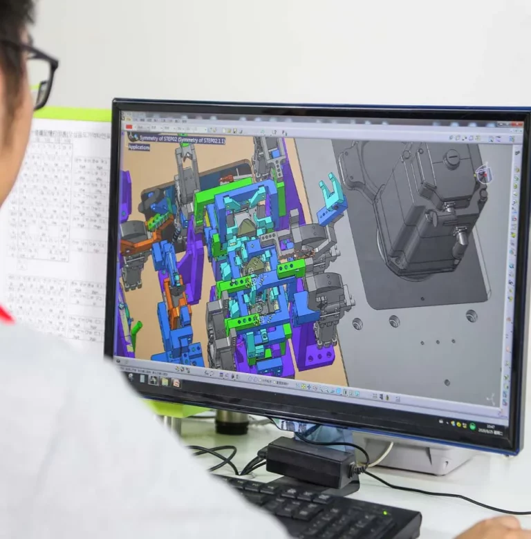
Digital tooling models can help engineers evaluate whether the proposed discharge route is geometrically feasible.
A design review should examine the relationship between scrap openings, die structure, supporting elements, press interfaces, and downstream collection equipment.
Useful review activities include:
- Checking the available discharge envelope.
- Reviewing clearances around moving components.
- Identifying potential scrap trapping locations.
- Confirming chute and conveyor alignment.
- Checking access for maintenance and cleaning.
- Reviewing potential interference during die installation.
These checks do not replace physical testing. Scrap behavior can depend on factors that are difficult to predict from geometry alone.
However, a structured design review can identify obvious restrictions before they lead to expensive modifications during tooling assembly or tryout.
For demanding automotive applications, the review should involve tooling design, manufacturing engineering, maintenance, and production personnel where appropriate.
9. Validate Scrap Evacuation During Tryout
A completed die should be evaluated under representative operating conditions before the scrap discharge arrangement is considered ready for production.
During tryout, engineers can observe whether scrap leaves the working area consistently and whether any offcuts accumulate during repeated press cycles.
Validation should include:
- Confirming that each scrap generation point has a functioning discharge path.
- Observing whether offcuts pass through openings without becoming trapped.
- Checking for interference with strip movement or component transfer.
- Inspecting the die for signs of scrap accumulation.
- Verifying that scrap reaches the intended collection equipment.
- Recording any abnormal discharge behavior.
- Implementing and verifying necessary design corrections.
Testing should be carried out under appropriate safety controls. Operators should never attempt to remove trapped scrap from an operating press or an unisolated die.
The objective is to confirm that the discharge arrangement works reliably under the intended production conditions, not merely that it appears acceptable during a stationary inspection.
10. Establish a Practical Scrap Management Checklist
A consistent checklist helps ensure that scrap handling is reviewed across tooling design, assembly, tryout, and production preparation.
Before tooling release, project teams should confirm:
- Scrap generation locations are documented.
- Expected scrap dimensions and shapes have been considered.
- Discharge openings provide sufficient clearance.
- Chutes do not contain obvious trapping points.
- Press and conveyor interfaces have been verified.
- Collection equipment can accommodate the expected scrap flow.
- Maintenance and cleaning access are practical.
- Scrap evacuation has been observed during tryout.
- Remaining issues have been recorded and resolved.
- Relevant maintenance and operating instructions are available.
The checklist should be adapted to the actual die configuration and production environment.
It is especially useful when a project involves multiple stations, complex offcuts, restricted press-bed space, or automated material handling.
11. Connect Scrap Evacuation with Overall Tooling Quality
Scrap evacuation is only one part of a successful automotive stamping die. It must work together with the cutting process, die structure, material handling, press operation, and production layout.
A well-designed discharge route cannot compensate for every tooling or process problem. Likewise, a precisely machined die may still experience operational interruptions if scrap is allowed to accumulate.
For this reason, scrap flow should be considered alongside the broader requirements for tooling performance and production readiness.
HONGXING, a member of TTM Group, develops automotive stamping dies for body structural components, reinforcement parts, brackets, and other sheet metal applications.
The engineering process can include tooling design, precision machining, die assembly, tryout, and production validation. Scrap evacuation requirements can be reviewed as part of the overall tooling layout, according to the component geometry and production system.
Learn more about HONGXING’s automotive stamping die solutions and automotive structural stamping dies.
Conclusion
Reliable scrap evacuation is an important consideration in automotive stamping die engineering. Poorly planned discharge paths can create scrap accumulation, interfere with tooling movement, and contribute to unnecessary production interruptions.
By identifying scrap generation points early, designing openings around actual offcut geometry, coordinating chutes with press and conveyor interfaces, and validating scrap flow during tryout, manufacturers can reduce avoidable handling problems.
The most effective approach is to treat scrap evacuation as an integral part of tooling design rather than a secondary detail.
For automotive stamping projects, a carefully reviewed scrap management arrangement supports safer maintenance, more predictable operation, and a cleaner production environment.
Discuss Your Automotive Stamping Die Project
HONGXING provides customized automotive stamping die solutions for automotive manufacturers and Tier 1 suppliers.
If your project involves complex trimming operations, multiple scrap discharge points, restricted press-bed space, or automated stamping production, share your component drawings and tooling requirements with our engineering team.
Request a Quote
Website: https://www.ttm-dieandtool.com/
Email: ttm@ttmgauge.com