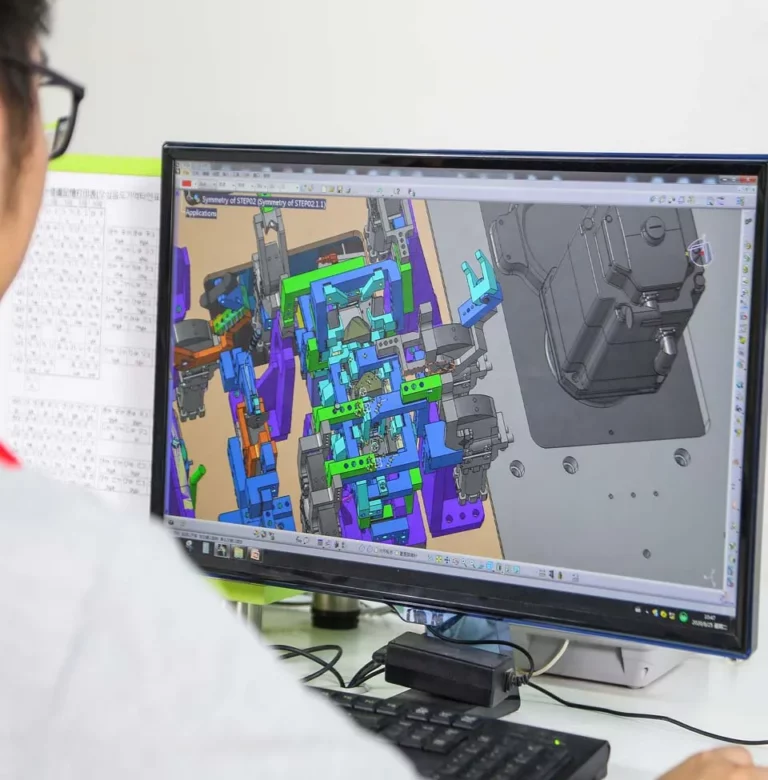


In high-volume automotive stamping production, scrap removal is an important part of overall tooling performance. During blanking, piercing, trimming, and notching operations, metal offcuts must be discharged from the die quickly and reliably. If scrap remains inside the tooling, it can interfere with subsequent press strokes, damage working surfaces, affect part quality, and cause unexpected production downtime.
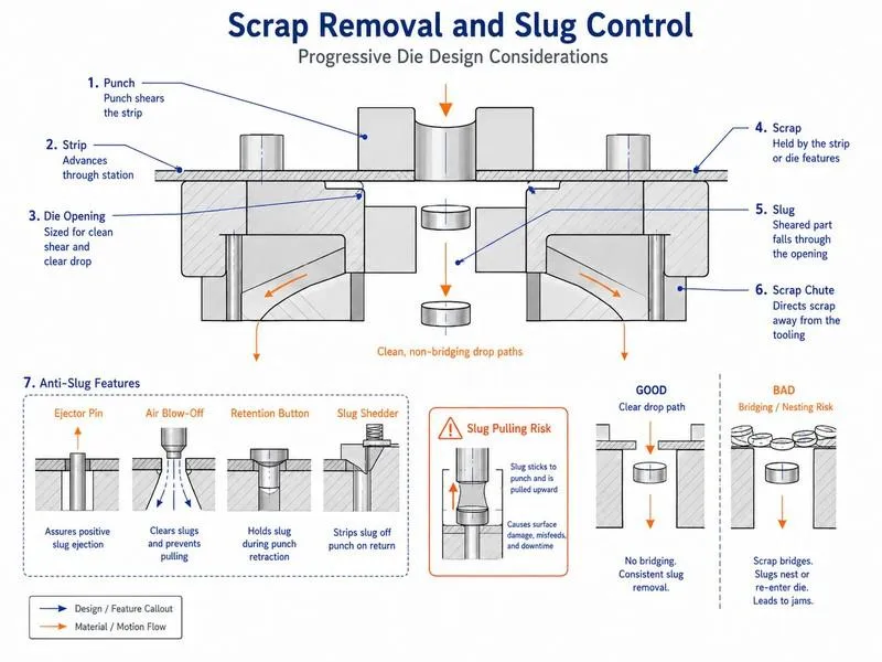
For automotive manufacturers and Tier 1 suppliers, effective scrap removal system design should be considered during the early stages of automotive stamping die development. A well-designed system helps maintain production continuity, simplifies die maintenance, and reduces the risk of scrap-related tooling problems.
Why Scrap Removal Matters in Automotive Stamping Dies
Scrap is generated in many automotive stamping operations. Typical examples include piercing holes, trimming panel edges, cutting excess material, and removing unwanted sections from sheet metal blanks.
Although individual scrap pieces may be relatively small, their movement through a complex die can create significant engineering challenges.
Common problems include:
- Scrap accumulation around punches and cutting areas
- Blocked scrap openings or discharge chutes
- Scrap pieces returning to the working area
- Interference with part positioning
- Damage to die surfaces caused by trapped material
- Unexpected production stops for cleaning and inspection
In progressive dies, scrap management becomes especially important because several operations take place within one integrated tooling system. A blockage at one station may affect subsequent operations and interrupt the entire production sequence.
For this reason, scrap discharge should be treated as a functional part of die design rather than an afterthought.
1. Analyze Scrap Generation During Process Planning
The first step is to identify where scrap will be generated throughout the stamping process.
Engineers should review the part geometry, strip layout, operation sequence, cutting locations, and expected scrap shapes before finalizing the tooling structure.
Important questions include:
- Which operations generate scrap?
- What are the approximate dimensions and shapes of the scrap pieces?
- Can scrap pieces become trapped between tooling components?
- Does the scrap need to pass through the lower die?
- Are there multiple scrap discharge points?
- Can scrap be removed without interfering with the finished component?
The answers help determine the location and size of discharge openings, the direction of scrap movement, and whether additional removal mechanisms are required.
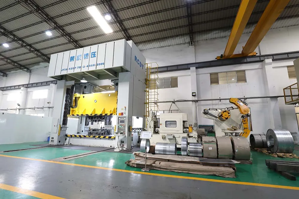
For complex multi-station tooling, this analysis should be coordinated with the overall automotive progressive die design so that scrap removal works together with material feeding, part transfer, and station layout.
2. Design Scrap Chutes for Reliable Discharge
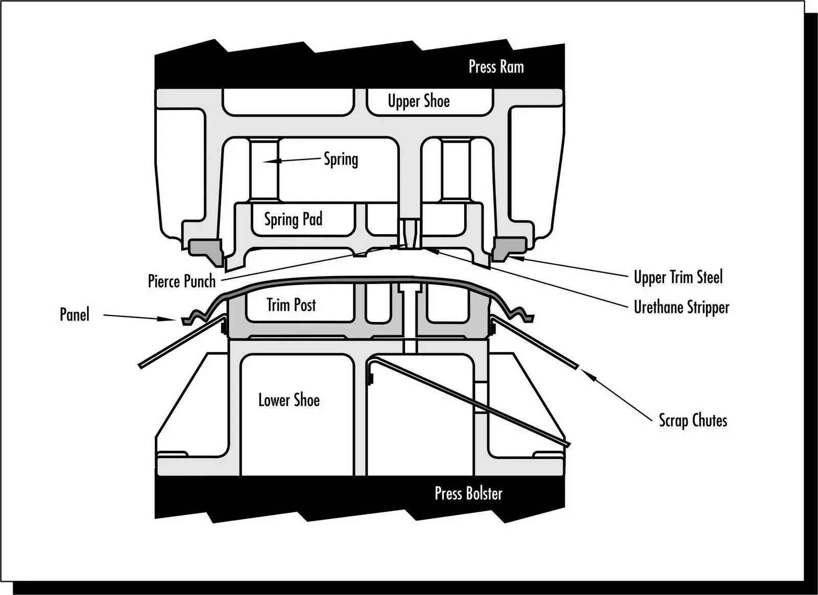
Scrap chutes provide a path for metal offcuts to leave the die area.
Their effectiveness depends on several factors, including scrap geometry, chute inclination, surface condition, available space, and the possibility of material accumulation.
A chute that works well for small, lightweight offcuts may not be suitable for larger or irregularly shaped scrap pieces.
During design, engineers should consider:
- Sufficient clearance for the expected scrap dimensions
- A suitable discharge direction
- Smooth transitions between openings and chutes
- Minimal obstruction from nearby die components
- Access for cleaning and maintenance
- Compatibility with the downstream scrap collection system
Gravity discharge can be effective when the die structure and scrap geometry permit a clear downward path. However, gravity alone may not be sufficient for long, flat, curled, or irregular pieces.
The design should therefore be evaluated against actual scrap characteristics instead of relying on a standard chute arrangement for every application.
3. Prevent Scrap Jamming Around Cutting Areas
Scrap jamming can occur when an offcut remains attached to the sheet, becomes trapped in a narrow opening, or is carried back toward the cutting area.
Several factors can contribute to this problem:
- Incomplete separation during cutting
- Incorrect punch and die clearance
- Worn cutting edges
- Scrap geometry that promotes hooking or rotation
- Insufficient discharge clearance
- Poorly positioned discharge openings
The appropriate corrective action depends on the actual cause.
For example, if scrap remains attached because cutting conditions are unstable, changing the chute alone may not solve the problem. Engineers may need to inspect cutting clearance, tool condition, punch geometry, and material characteristics.
Similarly, if scrap separates correctly but cannot pass through the discharge opening, the opening and downstream path may require redesign.
A systematic diagnosis helps avoid temporary adjustments that solve one blockage while creating another problem elsewhere in the die.
4. Consider Air Ejection and Mechanical Scrap Removal
Some stamping applications require additional assistance to move scrap away from the cutting area.
Depending on the tooling design, possible solutions include:
Air-assisted discharge: Controlled air flow can help move suitable lightweight scrap pieces away from critical areas. Air direction, pressure, timing, and containment should be evaluated carefully to avoid scattering scrap or disturbing other operations.
Mechanical ejection: Ejectors or other mechanical arrangements can help release scrap that would otherwise remain trapped. Their movement must be coordinated with the press stroke and the surrounding tooling structure.
Conveyor-based collection: A conveyor or centralized collection system can transport discharged scrap away from the press area, particularly where production generates a continuous volume of offcuts.
These solutions are not interchangeable. The appropriate arrangement depends on scrap size, weight, shape, production rate, available space, maintenance requirements, and the existing press-line configuration.
The objective is to establish a reliable path from the point where scrap is generated to the designated collection area.
5. Integrate Scrap Removal With Die Structure
Scrap discharge openings and channels must be coordinated with the strength and functionality of the die.
Large or poorly positioned openings can reduce the available space for supporting structures, fastening points, guide components, and other tooling elements.
For large automotive stamping dies, engineers must also consider structural rigidity, lifting and handling requirements, machining accessibility, and assembly conditions.
This is particularly relevant to heavy-duty tooling used for vehicle body and structural components.
For example, large automotive stamping dies require careful coordination between die structure, machining, assembly, and production requirements. Scrap discharge arrangements should fit within the overall tooling design without compromising critical structural functions.
A coordinated design review can identify potential conflicts before machining begins, when changes are generally easier to incorporate than after the die has been assembled.
6. Use Sensors When Scrap Detection Is Necessary
For selected high-volume stamping applications, sensors can help detect conditions associated with scrap accumulation or incomplete discharge.
Depending on the application, detection systems may monitor:
- Scrap passage through a defined location
- The presence of material in a critical area
- Abnormal conditions around a discharge mechanism
- Signals associated with a potential blockage
However, a sensor does not automatically guarantee that the scrap path is clear. Its effectiveness depends on the detection method, sensor location, scrap characteristics, and control logic.
Engineers should define what condition the sensor is intended to detect and how the press or production system should respond to an abnormal signal.
Where the risk justifies it, the detection system can be integrated into the machine control strategy to trigger an alarm or an appropriate controlled stop.
The final arrangement must be validated under realistic production conditions and coordinated with the press manufacturer’s control and safeguarding requirements.
7. Validate Scrap Discharge During Die Tryout
A scrap removal system should be tested during die tryout, not only checked visually during assembly.
The purpose is to verify that scrap can leave the tooling consistently under representative operating conditions.
A practical validation process includes:
- Inspect the scrap openings, channels, and discharge paths before testing.
- Confirm that all relevant tooling components are installed and correctly aligned.
- Run controlled trial strokes according to the approved tryout procedure.
- Observe scrap separation and movement at each relevant station.
- Check for accumulation, blockage, rebound, or interference.
- Inspect the tooling for signs of trapped scrap or unexpected contact.
- Correct identified problems and repeat the validation.
Testing should cover relevant material conditions, scrap shapes, and production settings within the approved operating range.
For complex tooling, repeated observations may be necessary because a scrap path that appears clear during a short trial may behave differently during sustained production.
The wider automotive stamping die tryout process provides an opportunity to evaluate scrap discharge alongside part quality, dimensional accuracy, and overall tooling performance.
8. Make Maintenance and Cleaning Practical
Even a well-designed scrap removal system requires inspection and maintenance.
Over time, scrap residue, lubricant, surface wear, damaged components, or changes in operating conditions can affect discharge reliability.
A practical maintenance plan should include:
- Removing accumulated scrap during approved maintenance procedures
- Inspecting chutes and openings for obstruction or damage
- Checking ejectors and other moving components
- Verifying that sensors and detection systems function correctly
- Examining cutting edges when recurring scrap problems occur
- Recording repeated blockage locations and corrective actions
Maintenance access should be considered during the design stage. Components that are difficult to inspect or clean can increase maintenance time and encourage incomplete cleaning.
Any inspection or cleaning work must follow the applicable machine safety procedures. Scrap should not be removed from hazardous tooling areas while the press is operating.
For further guidance, refer to the OSHA mechanical power press safety resource, which discusses press systems, tooling, material handling, inspection, and safeguarding considerations.
9. Evaluate Scrap Removal as Part of Overall Production Performance
Scrap discharge should be evaluated alongside other production performance indicators.
Useful measures include:
- Scrap-related stoppage frequency
- Average time required to clear a blockage
- Frequency of manual cleaning
- Scrap-related tooling damage
- Unplanned maintenance events
- Production interruptions associated with discharge problems
Tracking these indicators can help identify whether a problem originates in the discharge path, cutting process, tooling condition, material behavior, or downstream collection equipment.
For example, repeated blockages at the same station may indicate a local geometry problem. Blockages occurring across multiple stations may point toward a shared collection system or a broader process issue.
A data-based approach allows the engineering team to prioritize corrective actions according to actual production impact.
Conclusion
Reliable scrap removal is essential to maintaining stable automotive stamping operations. Poor discharge design can lead to blockages, tooling damage, quality issues, and avoidable downtime, even when the primary stamping operations are correctly designed.
Effective scrap removal system design begins with scrap analysis and process planning. It continues through chute design, jam prevention, appropriate ejection methods, structural integration, detection where necessary, tryout validation, and preventive maintenance.
For automotive tooling projects, these considerations should be addressed early in the engineering process and verified before production release.
HONGXING, a member of TTM Group, develops customized automotive stamping dies for demanding sheet metal manufacturing applications. By considering tooling structure, production requirements, maintenance access, and process reliability together, automotive manufacturers can build a stronger foundation for consistent high-volume production.
If you are developing a new automotive stamping die or addressing recurring scrap discharge problems, contact HONGXING to discuss your tooling requirements.