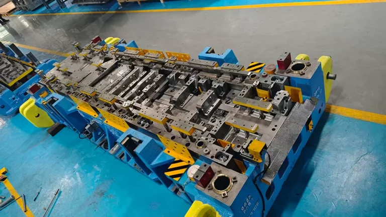


Tolerance stack-up in stamping dies,Tolerance stack-up is one of the most important factors affecting the dimensional accuracy and assembly performance of automotive stamping parts. A stamping die may contain hundreds of precision-machined components, and even when each individual component is within its specified tolerance, small deviations can accumulate and create a significant error in the final stamped part.
For automotive stamping dies, controlling tolerance stack-up requires more than simply improving machining accuracy. A reliable approach combines datum control, precision locating, proper die design, controlled machining, accurate assembly, and dimensional inspection.
What Is Tolerance Stack-Up in a Stamping Die?
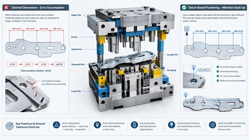
Tolerance stack-up in stamping dies occurs when multiple dimensional or positional variations accumulate along a dimension chain.
For example, if four sequential dimensions each have a tolerance of ±0.10 mm, the theoretical worst-case variation can reach ±0.40 mm.
This does not necessarily mean that every production part will experience the full ±0.40 mm variation. However, the example illustrates why a long chain of dependent dimensions can create dimensional instability.
In automotive stamping, this can affect:
- Hole-to-hole position
- Hole-to-edge distance
- Mounting locations
- Flange dimensions
- Formed features
- Assembly interfaces
- Gap and flushness
- Welding locations
Tolerance stack-up in stamping dies is particularly important in multi-station and progressive stamping dies, where dimensional variation can develop across several operations.
1. Establish a Unified Datum System
One of the most effective ways to reduce tolerance accumulation is to establish a consistent datum system at the beginning of the project.
Tolerance stack-up in stamping dies,The product drawing, stamping process, die design, machining process, checking fixture, and final inspection should ideally reference the same functional datum structure.
Instead of using:
Feature A → Feature B → Feature C → Feature D
a better approach is:
Common Datum → Feature A
Common Datum → Feature B
Common Datum → Feature C
Common Datum → Feature D
Tolerance stack-up in stamping dies,This prevents dimensional errors from being repeatedly transferred from one feature to the next.
Functional datums should also be stable and measurable. For formed automotive parts, critical dimensions may need to reference functional formed features rather than unstable raw blank edges.
2. Avoid Unnecessary Chain Dimensioning
Chain dimensioning is a common source of accumulated error.
Tolerance stack-up in stamping dies,Consider a stamped component with four hole locations. If each hole is positioned from the previous hole, the final hole position depends on all preceding tolerances.
A better strategy is to establish the hole pattern from a functional datum or locating feature.
This is particularly important for:
- Mounting holes
- Locating holes
- Slots
- Welding points
- Assembly interfaces
- Critical brackets
GD&T and positional tolerancing can be used to control the functional relationship between these features instead of relying entirely on a series of linear dimensions.
3. Use Precision Locating Pins
Bolts are primarily used to clamp components together; they should not be the only method used to establish precise positioning.
For critical die components, a combination of:
Locating Pins + Bolts
provides a much more repeatable positioning system.
Precision locating features are particularly important for:
- Die blocks
- Punch plates
- Inserts
- Forming blocks
- Guide components
- Replaceable die sections
When a component is removed for maintenance and later reinstalled, the locating system should allow it to return to its original position with minimal variation.
4. Control the Guide System
Tolerance stack-up in stamping dies,The guide system directly influences the relative alignment between the upper and lower die.
Important factors include:
- Guide post position
- Guide bush alignment
- Guide clearance
- Die shoe parallelism
- Perpendicularity
- Wear condition
- Assembly accuracy
Tolerance stack-up inside the guide system can change the actual alignment between punches and die openings. This can affect cutting clearance, hole position, burr formation, and tool life.
Therefore, die accuracy should not be evaluated only by checking individual machined components. The complete assembled die must also be evaluated.
5. Machine Critical Features From a Common Coordinate System
Machining strategy is another major factor in preventing tolerance accumulation.
For critical holes, pockets, locating features, and die profiles, it is preferable to establish a stable machining datum and machine important features from that common reference.
Avoid unnecessary processes such as:
Machine Feature A → Reposition → Use A as the new reference → Machine Feature B → Reposition again
Every unnecessary datum transfer creates another opportunity for positioning error.
Where practical, critical features should be completed in a single setup or controlled through a reliable datum-transfer strategy.
Modern stamping die manufacturing commonly combines CNC machining, EDM, grinding, and precision fitting to control critical die geometry.
6. Control Tolerance During Die Assembly
Tolerance stack-up in stamping dies,A common mistake is to assume that if every die component is individually within tolerance, the complete die will automatically be accurate.
This is not always true.
For example:
Upper die component tolerance
- lower die component tolerance
- locating tolerance
- guide-system tolerance
- assembly variation
can influence the final working relationship between the punch and die.
Therefore, assembly should include verification of:
- Upper and lower die alignment
- Die center
- Guide system
- Locating pins
- Insert positions
- Die clearance
- Shut height
- Critical forming surfaces
The objective is to control the assembled tooling system, rather than simply inspecting individual components.
7. Analyze Tolerance Stack-Up Before Manufacturing
Tolerance analysis should ideally be performed during the die design stage rather than after the first trial.
For a critical dimension, engineers can identify all features that contribute to the final result and calculate their possible variation.
Two common approaches are:
Worst-Case Analysis
Tolerance stack-up in stamping dies,The maximum possible variation is calculated by assuming every tolerance moves toward the unfavorable direction.
For example:
±0.10 + ±0.10 + ±0.10 = ±0.30 mm
This approach is conservative and useful for critical functional requirements.
Statistical / RSS Analysis
Root Sum Square (RSS) analysis considers the statistical nature of independent variations.
For three independent ±0.10 mm contributors:
√(0.10² + 0.10² + 0.10²) ≈ ±0.17 mm
The appropriate method depends on the functional requirement, production process, and customer specification.
The important point is to identify the stack-up before cutting steel, when design changes are still relatively inexpensive.
8. Consider Material Springback and Process Variation
Not all dimensional variation comes from the die itself.
Automotive stamping materials can exhibit:
- Springback
- Thickness variation
- Yield-strength variation
- Material anisotropy
- Friction variation
- Elastic recovery
High-strength and advanced high-strength steels can be particularly sensitive to springback. Therefore, simply tightening die machining tolerances does not automatically solve part dimensional problems. Die design may need forming compensation and process optimization.
This is why stamping accuracy should be evaluated as a combination of:
Die Accuracy + Material Behavior + Forming Process + Press Conditions
9. Use CMM and 3D Scanning for Verification
Tolerance stack-up in stamping dies,Dimensional inspection should close the loop between design and manufacturing.
For critical stamping dies and parts, inspection methods may include:
CMM Inspection
Useful for checking:
- Hole position
- Datum location
- Feature position
- Flatness
- Parallelism
- Critical dimensions
3D Scanning
Useful for evaluating:
- Formed surfaces
- Complex contours
- Overall deviation
- Forming areas
- Surface transitions
The inspection results can then be compared against CAD data to identify whether the variation comes from machining, assembly, forming, springback, or another process factor.
Automotive sheet-metal variation can also change during assembly, making consistent datum strategies between the die, checking fixture, and measurement system particularly important.
10. Build a Closed-Loop Die Tryout Process
A robust automotive stamping die development process should follow a closed loop:
Design → Simulation → Machining → Assembly → Tryout → Measurement → Correction → Validation
Rather than correcting every dimensional problem by manually modifying the die, engineers should identify the root cause of the variation.
For example:
Hole position is incorrect
The cause could be:
- Incorrect die datum
- Punch location error
- Die button location error
- Guide alignment
- Material movement
- Springback
- Fixture positioning
- Measurement datum mismatch
Finding the root cause is much more effective than simply adjusting the final feature.
Conclusion
Preventing tolerance stack-up in automotive stamping dies is fundamentally a system-level dimensional control problem.
The most effective practices include:
- Establish a unified datum system.
- Avoid unnecessary chain dimensioning.
- Use precision locating pins for critical components.
- Maintain accurate guide systems.
- Machine critical features from common references.
- Minimize unnecessary datum transfers.
- Perform tolerance stack-up analysis before manufacturing.
- Consider material springback and forming variation.
- Verify tooling and parts with CMM or 3D scanning.
- Use a closed-loop tryout and correction process.
The goal is not to make every dimension extremely tight. Instead, the goal is to control the functional dimensions that determine part fit, assembly, and performance.
For automotive stamping die manufacturing, a well-designed datum structure combined with controlled machining, precision assembly, and reliable dimensional inspection can significantly reduce cumulative errors and improve long-term production stability.