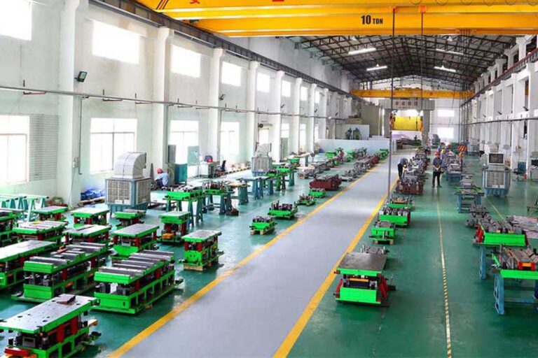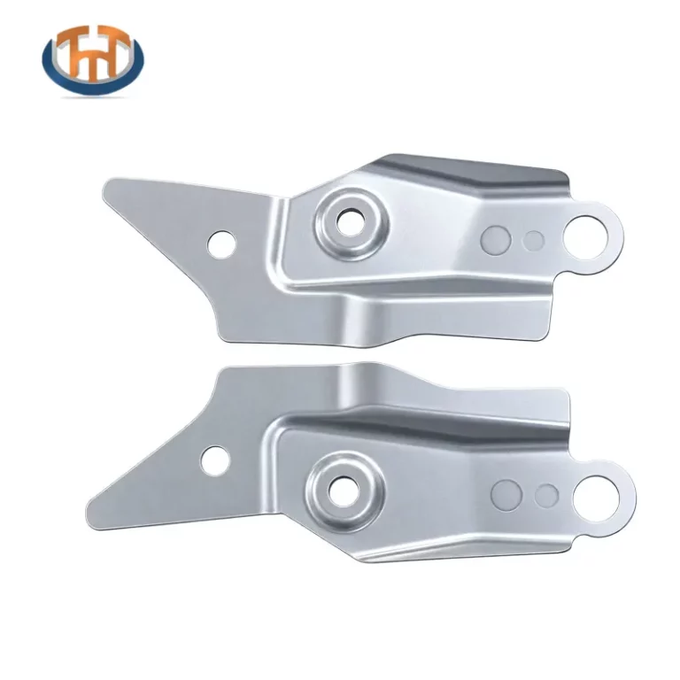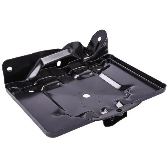


Selecting the correct stamping press is a critical step in automotive die development. The press must provide sufficient force, energy, and operating capability to complete the required forming and cutting operations without compromising tooling performance or production stability.
An undersized press may result in incomplete forming, excessive deflection, or unexpected equipment overload. On the other hand, selecting a press based only on maximum tonnage, without considering energy requirements, slide motion, and load distribution, can create other engineering challenges.
Accurate stamping press tonnage calculation helps tooling engineers evaluate press capacity during the early stages of automotive stamping die design. It also supports better coordination between die engineering, manufacturing, tryout, and production planning.
1. Understand the Main Types of Stamping Force
The required press force depends on the operations performed by the die. Automotive stamping tools may combine blanking, piercing, bending, drawing, trimming, and other forming processes.
Each operation creates different loading conditions.
Blanking and Piercing Force
Blanking and piercing involve separating sheet metal along a defined cutting edge. The required force depends primarily on the total cutting perimeter, material thickness, and material shear strength.
Bending Force
Bending force is influenced by material strength, thickness, bend length, die opening, forming geometry, and the selected bending method.
A simple cutting-force formula cannot be used to calculate every bending operation accurately.
Drawing and Forming Force
Drawing and complex forming operations involve material deformation, friction, material flow, and contact between the sheet and tooling surfaces.
Their force requirements depend on the component geometry, material properties, blank dimensions, forming sequence, and process conditions.
When a die combines several operations, engineers should evaluate the individual loads and determine the actual combined loading conditions rather than relying on a single generic force estimate.
2. Calculate Blanking and Piercing Force
For many cutting operations, the theoretical cutting force can be estimated using the following formula:
F = L × t × τs
Where:
- F = theoretical cutting force in newtons (N)
- L = total cutting perimeter in millimeters (mm)
- t = material thickness in millimeters (mm)
- τs = material shear strength in newtons per square millimeter (N/mm²)
For example, consider a steel component with a total effective cutting perimeter of 1,200 mm, a material thickness of 1.5 mm, and an assumed shear strength of 300 N/mm².
The estimated cutting force is:
F = 1,200 × 1.5 × 300
F = 540,000 N = 540 kN
To convert this value into metric tonnes-force:
540 ÷ 9.80665 ≈ 55.1 tonnes-force
This result represents the theoretical cutting force for the stated assumptions. It is not, by itself, a complete press-selection recommendation.
Actual press selection must also account for the full tooling operation, applicable load factors, the force-displacement relationship, and the manufacturer’s equipment specifications.
For progressive dies, engineers should determine which cutting and forming operations occur simultaneously during each press stroke.
3. Evaluate the Combined Load of the Die
An automotive stamping die may perform several operations within one cycle.
For example, a progressive die may pierce holes at one station, trim material at another station, and form a feature at a third station.
The press must accommodate the combined load generated by operations occurring at the same time.
However, simply adding the maximum force of every operation may produce an inaccurate result if the loads peak at different points during the stroke.
A more reliable engineering assessment considers:
- The force required by each operation.
- The position of each operation within the press stroke.
- Whether cutting and forming loads occur simultaneously.
- The expected peak force and its timing.
- The distribution of force across the die.
- The effect of the selected operating speed.
For complex tooling, the force-displacement curve provides more useful information than a single theoretical tonnage value.
The final assessment should reflect the actual process sequence and operating conditions.
4. Check Press Capacity at the Required Stroke Position
A press rated for a particular tonnage does not necessarily deliver that force at every point in its stroke.
Mechanical presses commonly have a specified rated-capacity position, often defined near the bottom of the stroke. Available force can be lower at other positions, depending on the press design.
This distinction is important for forming operations that generate substantial force before the slide reaches the bottom of its stroke.
Before selecting a press, engineers should review:
- Rated press capacity and its specified measurement position.
- Slide stroke and shut height.
- Available adjustment range.
- Die height and mounting requirements.
- Permitted operating speed.
- Manufacturer-provided load and capacity curves.
The peak force must remain within the press manufacturer’s permitted operating limits at the relevant slide position.
This check is particularly important for deep drawing and other operations with demanding load profiles.
5. Consider Energy Requirements and Press Speed
Press tonnage is only one part of the selection process. The press must also supply sufficient energy during the working portion of the stroke.
Energy requirements depend on the work performed during deformation and cutting, as well as the operating characteristics of the press.
A press may have sufficient nominal tonnage but still be unsuitable if its available energy, flywheel capacity, or drive system cannot support the intended production conditions.
Press speed also affects production performance. Increasing strokes per minute can change the available time for material movement, transfer operations, lubrication, and part handling.
For automated automotive stamping lines, press selection should therefore consider both the force required to complete the operation and the energy available at the intended production speed.
6. Evaluate Off-Center Loading and Die Stability
The distribution of force across the die can be as important as the total force.
If cutting or forming loads are concentrated on one side of the tooling, they may create an unbalanced load on the press slide.
Potential consequences include:
- Uneven loading of the press structure.
- Slide or bolster deflection.
- Changes in tooling alignment.
- Uneven wear of guide components.
- Dimensional variation in stamped parts.
Engineers should evaluate the location of the load relative to the press centerline and the permitted eccentric loading specified by the press manufacturer.
For tooling with multiple stations or asymmetric component geometry, load distribution deserves particular attention.
Proper die layout, structural rigidity, and press compatibility help reduce the risk of uneven loading during production.
7. Include Material and Process Variations
The force calculated during initial engineering is based on defined assumptions. Actual production conditions may vary.
Important variables include material grade, thickness tolerance, mechanical properties, lubrication, cutting-edge condition, and changes in forming behavior.
High-strength steel applications may require particular attention to material strength, forming loads, and tooling durability.
Engineers should use reliable material data and appropriate process calculations rather than applying one fixed tonnage multiplier to every die.
Any design allowance or safety margin should be justified by the process requirements, the uncertainty in the calculations, and the equipment manufacturer’s guidance.
The goal is to establish a defensible operating range rather than simply choosing the largest available press.
8. Verify Press Compatibility Before Die Manufacturing
Press compatibility should be checked before detailed tooling manufacturing begins.
In addition to tonnage, engineers should confirm the physical and operational interfaces between the die and the selected press.
Key checks include:
- Bolster dimensions and mounting positions.
- Slide dimensions and mounting arrangements.
- Maximum and minimum die height.
- Slide stroke and adjustment range.
- Feed and transfer equipment clearance.
- Material handling and part discharge requirements.
- Available automation interfaces.
- Press and tooling safety requirements.
These checks help prevent late-stage modifications caused by insufficient installation space, incompatible mounting arrangements, or incorrect equipment assumptions.
For automotive stamping projects, press selection should be coordinated with the overall tooling development plan and the requirements of the intended production line.
9. Validate the Calculation During Die Tryout
Engineering calculations establish the initial design basis, but actual tooling performance must be verified under representative operating conditions.
During die tryout, engineers can assess whether the selected press operates within its permitted limits and whether the tooling performs as intended.
Depending on the project, validation may include:
- Confirming press setup and die installation.
- Reviewing available press load-monitoring data.
- Checking for abnormal noise or vibration.
- Inspecting stamped part quality.
- Evaluating material feeding and transfer.
- Checking for signs of uneven loading.
- Confirming stable operation at the intended production conditions.
If unexpected loads or quality issues arise, the engineering team should investigate the underlying cause before changing press settings or modifying the tooling.
For a broader overview of this process, see our guide to automotive stamping die tryout.
10. How Press Selection Supports Reliable Automotive Tooling
Press selection is part of a wider engineering process that connects component geometry, material properties, die design, manufacturing, assembly, and production validation.
An effective selection process helps ensure that the press can accommodate the required force, energy, stroke, operating speed, and tooling dimensions.
For automotive manufacturers and Tier 1 suppliers, these considerations are particularly important when developing tooling for structural reinforcements, brackets, cross members, and other precision sheet metal components.
HONGXING, a member of TTM Group, specializes in automotive stamping die engineering and manufacturing. Its automotive stamping die solutions support tooling development for a range of automotive sheet metal applications.
By evaluating press requirements early and coordinating them with tooling design and manufacturing, engineering teams can reduce compatibility risks and establish a more reliable foundation for production.
Conclusion
Accurate stamping press tonnage calculation involves more than estimating the cutting force or selecting a press based on its maximum rated capacity.
Engineers must evaluate the combined loads of the tooling, the position of peak force within the stroke, energy requirements, operating speed, load distribution, and physical compatibility between the press and die.
A systematic approach to press selection helps reduce equipment overload risks, improve tooling compatibility, and support stable automotive stamping production.
For new automotive stamping die projects, HONGXING works with customers to develop tooling solutions that consider component requirements, manufacturing processes, and production needs.
Visit HONGXING Automotive Stamping Die Solutions to learn more about our tooling capabilities, or contact our team to discuss your project requirements.